Electromagnetic Radiation

Wave & particle models, radiation laws, and how EM energy interacts with the atmosphere and Earth's surface.

slide 1

Introduction to Remote Sensing

Four topics covered in this deck:

  • Electromagnetic radiation principles
  • Electromagnetic radiation models (wave + particle)
  • Energy interactions in the atmosphere
  • Energy interactions with Earth-surface features
Likely answer edit

Deck scope — four big topics.

  1. EM radiation principles — wave vs particle, wavelength/frequency, energy.
  2. EM radiation models — the wave model and the particle/quantum model.
  3. Energy interactions in the atmosphere — scattering, absorption, transmission.
  4. Energy interactions with Earth-surface features — reflection, absorption, transmission at the target.
slide 2 (picture)

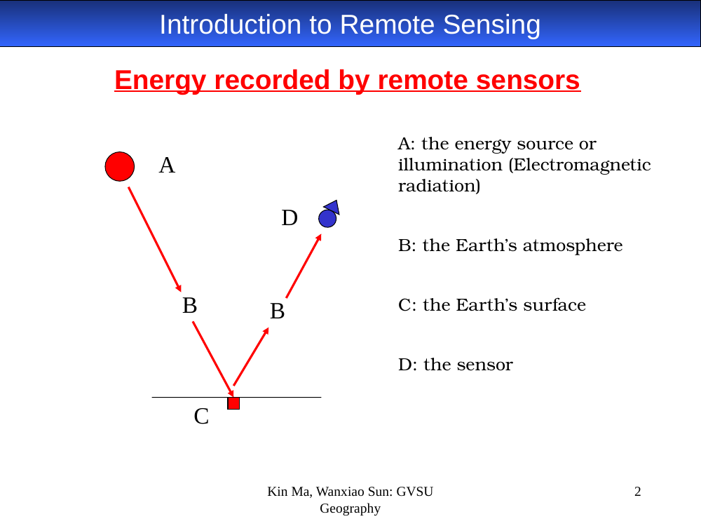
Energy recorded by remote sensors

Remote sensing energy path diagram
In-image text (for later study-guide use)

Diagram labels:

  • A — the energy source or illumination (EM radiation).
  • B — the Earth's atmosphere (shown on both the downward and upward paths).
  • C — the Earth's surface.
  • D — the sensor.
Likely answer edit

The four elements in every passive optical remote-sensing chain — memorize the letters.

  • A — the energy source / illumination (usually the Sun for optical; the sensor itself for active systems like radar).
  • B — the Earth’s atmosphere (traversed twice for reflected solar: down then back up).
  • C — the Earth’s surface (the target — reflects/absorbs/transmits).
  • D — the sensor (records the radiance that reaches it).
slide 3

Electromagnetic energy / radiation models

  • Wave model
  • Particle model
Likely answer edit

Two complementary models of EM energy. Neither alone is complete; both describe the same radiation.

  • Wave model — best for describing propagation, wavelength, frequency, polarization.
  • Particle (quantum) model — best for describing energy content and interaction with matter (absorption, emission).
slide 4 (picture)

Wave model

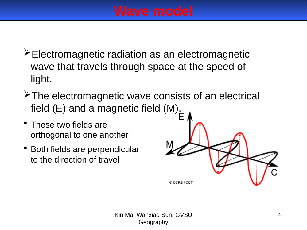
Electromagnetic radiation behaves as a wave traveling through space at the speed of light. The wave has an electric field (E) and a magnetic field (M) — orthogonal to each other, and both perpendicular to the direction of travel.

EM wave diagram — E and M fields
In-image text (for later study-guide use)

Diagram shows the classic EM wave: a red sinusoid (E, vertical) and a black sinusoid (M, horizontal) propagating along axis C. Credit: CCRS/CCT.

Likely answer edit

Wave model. EM radiation is a transverse wave traveling through vacuum at the speed of light (c = 3 × 10⁸ m/s).

  • The wave carries an electric field E and a magnetic field M.
  • E and M are perpendicular to each other and both are perpendicular to the direction of propagation.
slide 5 (formula)

Wave equation

$$ \lambda = \frac{c}{\nu} \qquad\text{(equivalently } c = \lambda\,\nu\text{)} $$
  • λ (lambda) — wavelength, the distance from one wave peak to the next. Units: µm.
  • c — speed of light, 3 × 10⁸ m/s.
  • ν (nu) — frequency, Hz (cycles per second).
Likely answer edit

Wave equation.

λ = c / ν (equivalently c = λν)

  • λ (lambda) — wavelength (peak-to-peak distance), typical units µm (1 µm = 10⁻⁶ m).
  • c — speed of light, 3 × 10⁸ m/s.
  • ν (nu) — frequency, Hz (cycles per second).

  • Key takeaway: wavelength and frequency are inversely related. Long wavelength ↔ low frequency ↔ low energy (see slide 9).
slide 6 (picture)

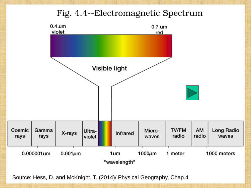
The electromagnetic spectrum

Electromagnetic spectrum chart
In-image text (for later study-guide use)

Chart labels, shortest → longest wavelength:

Cosmic rays | Gamma rays | X-rays | Ultraviolet | Visible (0.4 – 0.7 µm) | Infrared | Microwaves | TV/FM radio | AM radio | Long radio waves

Visible detail: violet end 0.4 µm, red end 0.7 µm.

Scale ticks shown: 0.000001 µm · 0.001 µm · 1 µm · 1000 µm · 1 meter · 1000 meters.

Source: Hess, D. and McKnight, T. (2014) Physical Geography, Chap. 4.

Likely answer edit

The EM spectrum (Hess & McKnight, 2014). Bands arranged by wavelength, shortest to longest:

Band Wavelength
Cosmic rays < 0.00001 µm
Gamma rays ~ 0.0001 µm
X-rays ~ 0.001 – 0.01 µm
Ultraviolet ~ 0.01 – 0.4 µm
Visible 0.4 – 0.7 µm
Infrared 0.7 – 1000 µm
Microwaves 1 mm – 1 m
TV / FM radio ~ 1 m
AM radio ~ 100 m
Long radio waves > 1 000 m
  • Most Earth-observation sensors live in visible, near-IR, mid-IR, thermal-IR, and microwave windows.
slide 7

The electromagnetic spectrum — definition

The EM spectrum is a continuous spectrum of all electromagnetic waves, arranged according to frequency and wavelength.

Likely answer edit

The EM spectrum is continuous — the “bands” we name (visible, IR, etc.) are just convenient regions of a continuum of waves, ordered by frequency and wavelength.

slide 8

Electromagnetic spectrum — visible light

Light is the particular band of EM radiation that the human eye can see and sense: 0.4 – 0.7 µm. Everything else in the spectrum — UV, infrared, microwave, radio — is EM radiation we can't see directly.

Likely answer edit

Visible light — only the narrow band 0.4 – 0.7 µm is detectable by the human eye, out of a spectrum that spans more than twelve orders of magnitude. Nearly all of “remote sensing” lives outside what we can see.

  • Violet ≈ 0.4 µm, blue ≈ 0.45, green ≈ 0.55, red ≈ 0.65–0.7 µm.
slide 9 (formula)

Particle theory — the quantum / photon

EM radiation is composed of discrete packets called quanta (or photons). Each photon carries energy:

$$ Q = h\nu = \frac{hc}{\lambda} $$
  • Q — energy of a quantum, in Joules.
  • h — Planck's constant, 6.626 × 10⁻³⁴ J·s.
  • ν — frequency (Hz); λ — wavelength.

Therefore: longer wavelength → lower energy per photon. Sensors at long wavelengths (thermal, microwave) must view larger ground areas to collect a detectable signal.

Likely answer edit

Particle (quantum) theory. EM radiation is made of discrete packets — quanta (also called photons).

Q = hν = hc / λ

  • Q — energy of a quantum, Joules.
  • h — Planck’s constant, 6.626 × 10⁻³⁴ J·s.
  • ν — frequency (Hz); λ — wavelength.

  • Longer wavelength → lower energy per photon. That’s why long-wavelength sensors (thermal, microwave) must view larger ground areas — they need a bigger footprint to collect enough energy for a detectable signal.
slide 10 (formula)

Stefan–Boltzmann Law

Every object above absolute zero (0 K = −273 °C) emits EM radiation. The total emitted power per unit area from a blackbody:

$$ M_\lambda = \sigma\,T^{4} $$
  • M_λ — total emitted radiation exiting the object, W/m².
  • σ — Stefan–Boltzmann constant, 5.6697 × 10⁻⁸ W·m⁻²·K⁻⁴.
  • T — absolute temperature in Kelvin.

Blackbody — an ideal, hypothetical radiator that totally absorbs and re-emits all incident energy. Real objects emit ε · σ · T⁴, where ε (emissivity) is between 0 and 1.

Likely answer edit

Stefan–Boltzmann law. Every object above absolute zero (0 K = −273 °C) emits EM radiation.

M_λ = σ · T⁴

  • M_λ — total emitted radiation per unit area (W/m²).
  • σ (sigma) — Stefan–Boltzmann constant, 5.6697 × 10⁻⁸ W·m⁻²·K⁻⁴.
  • T — absolute temperature in Kelvin.
  • The law assumes a blackbody — an ideal radiator that absorbs all incident energy and re-emits it. Real objects are described by M_λ = ε · σ · T⁴, where ε (emissivity, 0–1) is how close the object is to a true blackbody.

  • Key point: emitted energy scales with the fourth power of temperature — small temperature changes produce big radiance changes (why thermal sensors are sensitive).
slide 11 (formula)

Wien's Displacement Law

Gives the peak (dominant) emission wavelength of a blackbody from its temperature:

$$ \lambda_{max} = \frac{2897.8}{T} \qquad \text{(µm, with T in K)} $$
  • λ_max — wavelength of maximum emittance (µm).
  • T — temperature (K).
  • Sun (T ≈ 6000 K): λ_max ≈ 0.483 µm (visible / green-blue).
  • Earth (T ≈ 300 K): λ_max ≈ 9.66 µm (thermal infrared).

As a blackbody gets hotter, its peak wavelength gets shorter.

Likely answer edit

Wien’s displacement law. Gives the peak-emission wavelength of a blackbody:

λ_max = 2897.8 / T (λ_max in µm, T in K)

  • Sun (T ≈ 6000 K): λ_max ≈ 0.483 µm (green-blue visible light).
  • Earth (T ≈ 300 K): λ_max ≈ 9.66 µm (thermal infrared).

  • Consequence for sensors: use visible/NIR to measure reflected solar, and thermal infrared (8–14 µm) to measure emitted Earth radiation.
  • Hotter object → shorter peak wavelength (why a stove burner glows red, then orange, then white).
slide 12

Energy interactions in the atmosphere

All radiation detected by remote sensors has passed through some distance of atmosphere (the path length). The atmosphere does three things to radiation:

  • Scattering
  • Absorption
  • Transmission
Likely answer edit

Three things the atmosphere does to radiation passing through it:

  • Scattering — photons are redirected unpredictably by particles or molecules.
  • Absorption — photons are taken up by molecules (converted to heat or re-radiated).
  • Transmission — photons pass through unchanged (this is what we want for imaging).

  • Path length matters: low-sun / high-latitude imagery traverses more atmosphere and suffers more scattering + absorption.
slide 13

Atmospheric scattering — three types

  • Rayleigh scattering — wavelength ≫ particles (air molecules). Affects shorter wavelengths. Explains the blue sky.
  • Mie scattering — wavelength ≈ particles (dust, smoke, aerosols). Influences longer wavelengths / all of visible.
  • Non-selective scattering — wavelength ≪ particles (water droplets, ice crystals). Affects all wavelengths equally. Explains white clouds (B, G, R scattered equally).

Video reference from the slide: YouTube — scattering explanation (summary 7:22–9:22).

Likely answer edit

Three types of atmospheric scattering — classified by particle size relative to wavelength.

  • Rayleigh scattering — particles ≪ λ (air molecules). Inverse-λ⁴ dependence — affects shorter wavelengths most. Why the sky is blue.
  • Mie scattering — particles ≈ λ (dust, smoke, pollen, aerosols). Influences longer wavelengths / all visible. Creates hazy skies.
  • Non-selective scattering — particles ≫ λ (cloud droplets, ice). Affects all wavelengths equallyclouds appear white because blue, green, and red are all scattered in the same proportion.
slide 14

Atmospheric absorption

Molecules in the atmosphere absorb radiant energy at various wavelengths with different intensities.

  • Ozone (O₃) — absorbs harmful ultraviolet radiation.
  • Carbon dioxide (CO₂) — absorbs in the far infrared.
  • Water vapor (H₂O) — absorbs in the longwave infrared and shortwave microwave.
Likely answer edit

Selective atmospheric absorbers — different molecules absorb different wavelengths:

  • Ozone (O₃) — absorbs harmful ultraviolet (protects the biosphere).
  • Carbon dioxide (CO₂) — absorbs in the far infrared (thermal band, hence its role in the greenhouse effect).
  • Water vapor (H₂O) — absorbs in the longwave infrared and shortwave microwave.

  • Consequence: we can’t image at every wavelength — see slide 15 for the “windows” that do transmit well.
slide 15

Atmospheric windows

Portions of the spectrum where the atmosphere transmits EM radiation particularly well — these are where remote-sensing instruments are designed to operate:

  • visible
  • near-infrared
  • middle-infrared
  • thermal-infrared
  • microwave
Likely answer edit

Atmospheric windows — bands where the atmosphere is mostly transparent to EM radiation. Remote-sensing instruments are designed to fit inside them.

  • Visible (0.4 – 0.7 µm)
  • Near-infrared (0.7 – 1.3 µm)
  • Middle / short-wave infrared (1.3 – 3.0 µm, with gaps)
  • Thermal infrared (3.0 – 5.0 µm and 8 – 14 µm — the big thermal window)
  • Microwave (1 mm – 1 m) — used by radar; essentially all-weather.

  • Blocked regions (opaque) are dominated by H₂O and CO₂ absorption in the IR.
slide 16

Energy interactions with Earth's features

How can plants grow in the shade?

Energy incident on a body is reflected, absorbed, or transmitted:

  • Absorption — radiation is absorbed into the target.
  • Transmission — radiation passes through the target.
  • Reflection — radiation "bounces" off the target and is redirected.

The proportions of reflected / absorbed / transmitted energy vary for different features and different wavelengths.

Likely answer edit

Energy balance at the target“How can plants grow in the shade?” The answer is implied by this slide: diffuse/scattered light is still energy, and even shaded canopies receive enough for photosynthesis.

  • Energy incident on any body is either reflected, absorbed, or transmitted.
  • The proportions depend on:
    • The feature (leaf, water, concrete — each has its own spectral signature).
    • The wavelength (a leaf reflects little red, lots of NIR; a lake does the opposite).
  • Conservation: reflected + absorbed + transmitted = total incident energy (see slide 18).
slide 17

Active and passive remote sensing

(The original slide had a diagram that was lost in PDF conversion — see the likely-answer note below.)

Likely answer edit

Active vs. passive remote sensing (the slide’s diagram didn’t survive PDF conversion — here’s the concept in full).

  • Passive — the sensor only receives natural energy. The source is the Sun (reflected solar) or the target’s own thermal emission. Most optical/thermal imagers are passive. Examples: Landsat OLI/TIRS, MODIS, SPOT, IKONOS.
  • Active — the sensor emits its own energy pulse and measures what bounces back. Not Sun-dependent, works day or night, and usually penetrates clouds. Examples: RADAR, LiDAR, scatterometers, SRTM.

  • Short-answer mnemonic: Passive listens; active shouts and listens.
slide 18 (formula)

Reflected energy

Remote-sensing systems depend on reflected energy, measured as spectral reflectance (or just reflectance / spectral signature). Energy conservation at the target:

$$ \Phi_I(\lambda) = \Phi_R(\lambda) + \Phi_T(\lambda) + \Phi_A(\lambda) $$
  • Φ_I(λ) — total incident radiant flux at wavelength λ.
  • Φ_R(λ) — reflected energy.
  • Φ_T(λ) — transmitted energy.
  • Φ_A(λ) — absorbed energy.
Likely answer edit

Radiant flux budget at the target. For any wavelength λ, the incident flux Φ_I(λ) splits into three parts:

Φ_I(λ) = Φ_R(λ) + Φ_T(λ) + Φ_A(λ)

  • Φ_R — reflected energy.
  • Φ_T — transmitted energy.
  • Φ_A — absorbed energy.

  • Reflectance (ρ, rho): ρ(λ) = Φ_R(λ) / Φ_I(λ) — the fraction reflected at each wavelength. Plotted vs. λ, this gives a spectral signature (also called spectral reflectance curve) for a surface — the foundation of all optical classification.
slide 19

Types of reflection

  • Specular (mirror-like) — angle of incidence = angle of reflection. Example?
  • Lambertian (diffuse) — reflects energy uniformly in all directions. What is an example in the natural world?
  • Regular case — most bodies behave somewhere between ideal specular and diffuse reflectors.
Likely answer edit

Three reflection regimes.

  • Specular (mirror-like) — angle of incidence equals angle of reflection. Energy bounces in one direction only.
    • Examples: calm water surface, polished metal, wet pavement, glass.
  • Lambertian (perfectly diffuse) — energy reflects uniformly in all directions; brightness appears the same from every viewing angle.
    • Natural example: freshly fallen snow; matte dry sand; whitewashed walls. (No real surface is perfectly Lambertian — it’s an ideal.)
  • Regular / real surfaces — somewhere between the two. Most natural surfaces are diffuse-dominated with a specular component; this is why sensor geometry (BRDF) matters for precise measurements.
Deck: 2024_RemoteSensing2-EMR (1).pptx — 19 slides. Download original · Edit our reproduction